


Figure 9.
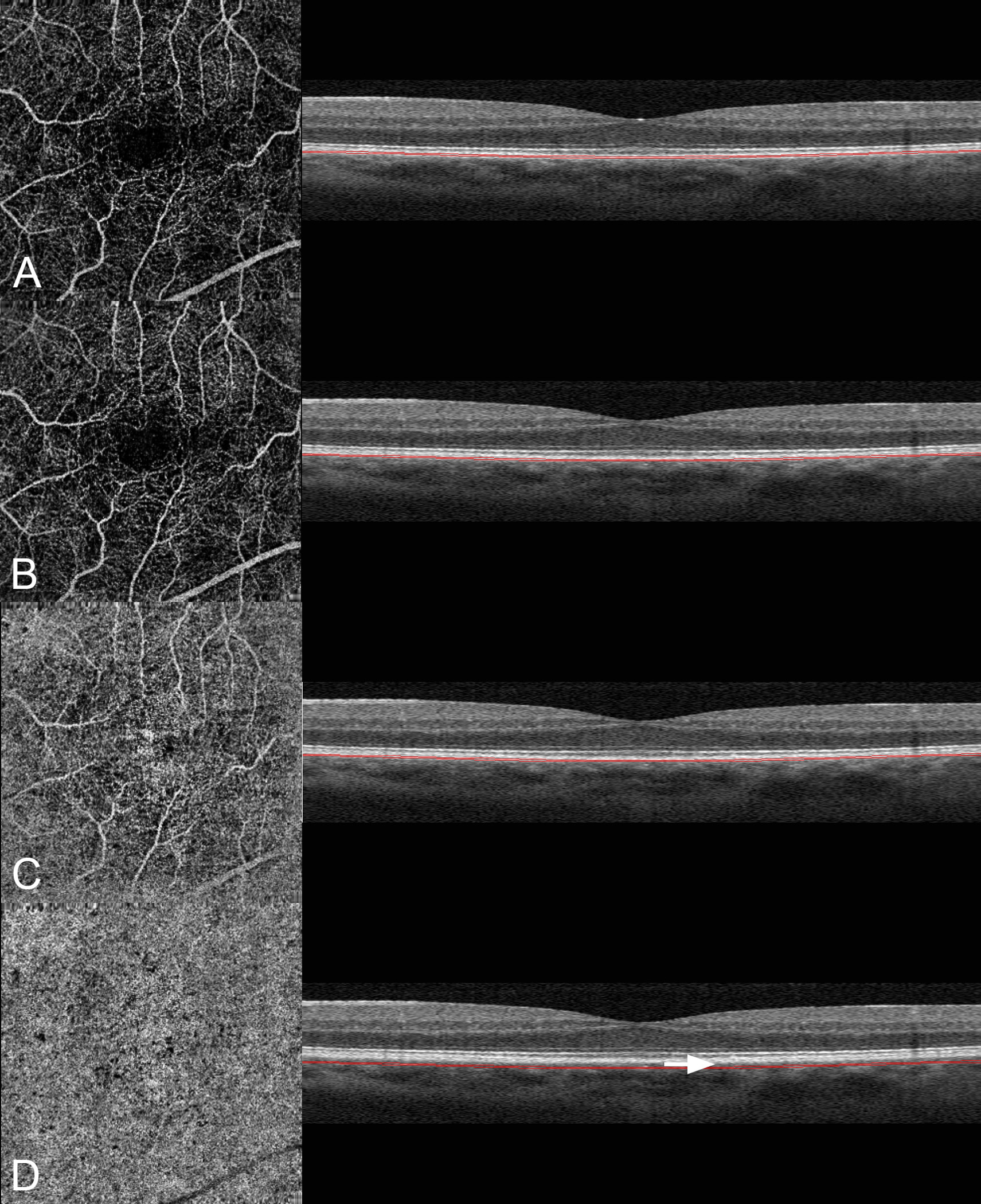
Images A through D are different layers of the same eye illustrated in Figure 6. On the left is the angiographic image and on the right a B-scan image showing the level at which the angiographic image was obtained. A. When the slab section is brought back to the level of the retinal pigment epithelium, a clear visualization of the retinal vessels is obtained. B. The thickness and anatomic location of the slab section was brought back to the level where the choriocapillaris resides. Note the image is dominated by retinal vascular projection. C. The slab section in (B) is displaced 15 microns further back into the choroid. Note that the angiographic image is getting brighter even though the corresponding area in the structural image is darker. The retinal vessels are less visible. D. The slab section is displaced an additional 20 microns into the choroid. The angiographic image shows a bright image suggestive of the choriocapillaris. Note the visible gap in the structural B-scan (arrow) separating the corresponding section and the expected anatomic location of the choriocapillaris.