


Fig. 1. Middle section through the LCP injector.
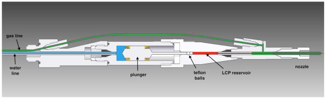
In operation, the device is attached via the leftmost threaded fitting to a nozzle rod (not shown) for insertion into the experimental chamber. Water (blue) and gas (green) lines are routed through the nozzle rod from the left, LCP (red) is extruded from the nozzle on the right. Water, at a pressure of up to 300 psi, drives the hydraulic plunger, which amplifies the pressure 34 times to drive LCP through a capillary with an inner diameter of 10–50 μm. Two spherical Teflon beads are used to provide a tight seal against a pressure of up to 10,000 psi. The co-flowing gas is necessary for reliable extrusion and to maintain co-axial flow.